Gyroscopic LED totem
There’s a handful of events I look forward to that are consistently highlights of my year, and Electric Daisy Carnival, the largest electronic music festival in the US, is always one of them. To say this festival is large is an understatement: almost 200,000 people pack into the Las Vegas Motor Speedway each year to be part of this 3-day music festival.
One of my favorite things about EDC is the totems. Basically you put a giant flag, meme, muppet character, stuffed animal, scrolling marquee, sex doll, Swiffer mop, or any other random crap on top of a pole and wave it around above the sea of people below to act as a beacon for your rave fam to find you. There’s usually enough people that cell service is nonexistent, so good luck finding your friends in a crowd of 50,000 people without one.
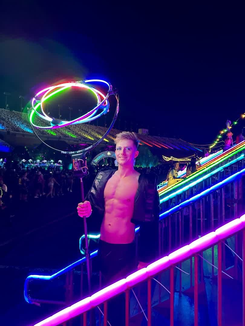
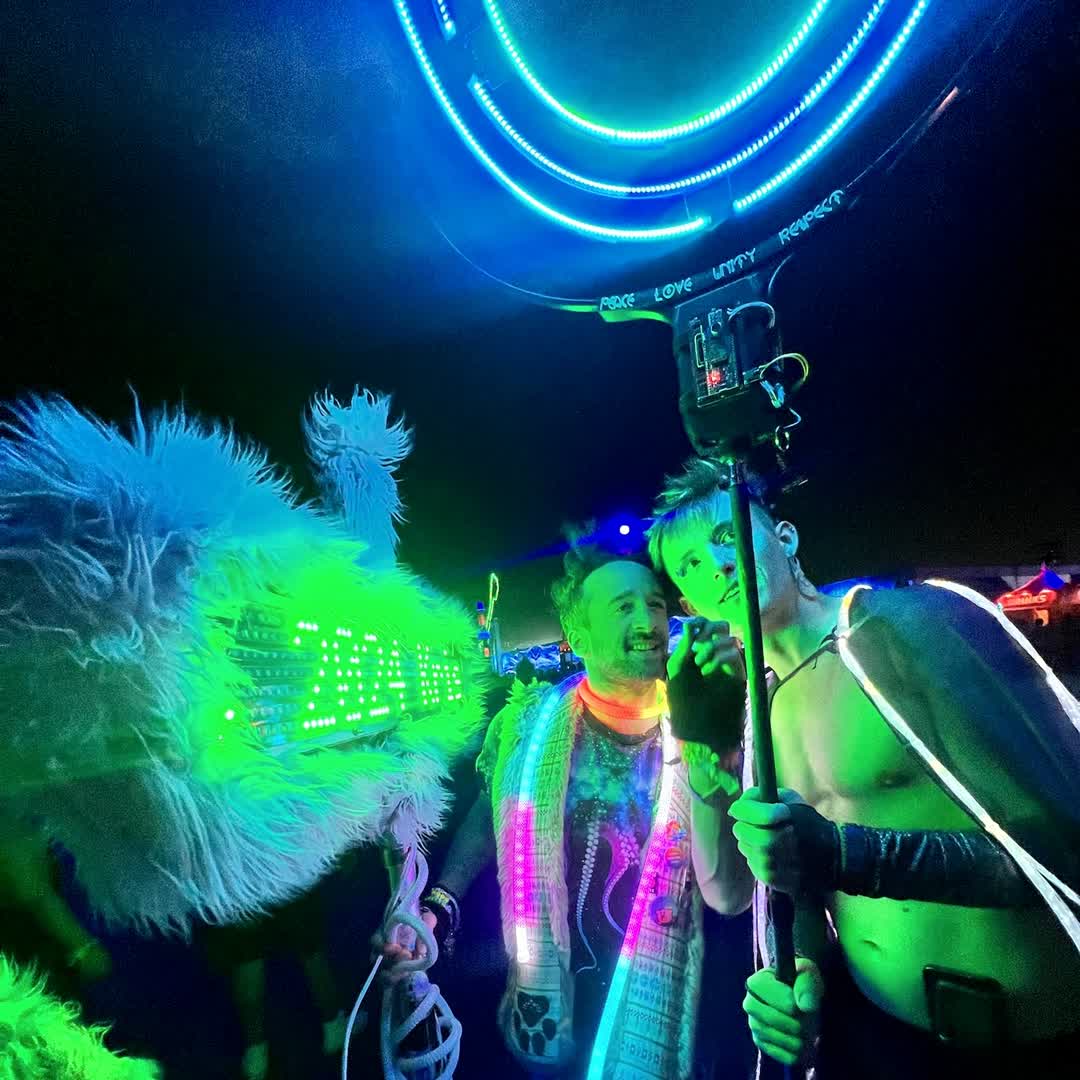
Totems are more than just functional items though — they can be portable artistic statements, mobile good-vibe dispensers, and something to stare at for a little too long while you’re tripping absolute balls. I’ve always loved the vibes totems bring to music festivals, and as someone who is prone to overkill when it comes to building things, I wanted to make one that would be noticed. So I put a giant gyroscope frame on a stick and made it dance to the music!
When I was first planning this out, some of the first questions I needed to answer were:
- What should I make the rings out of?
- How do I get power and signal transmission across rotating joints?
- How do I couple the rings together?
- How much torque will be required to move it?
- What do I use for the power source
- What do I use for the controller?
- How do I communicate with it (to change speed/lighting modes)?
- How do I get it to expressively dance to the music in a noisy environment?
Let’s start with the first question: what to make the rings out of. I would need something light and strong (even at these speeds, changing the angular momentum of a spinning ring puts a lot of torque on the ring outside it). The most obvious choice was aluminum, but this can be difficult to work with without having access to a welding machine or roller press. Fortunately, I was able to find a shop that sells supplies for store display fronts which had pre-welded aluminum rings of various diameters and thicknesses. I estimated the minimum spacing between rings I would need to be 2 inches, and I bought the largest three rings consecutively offset by that distance that they sold.
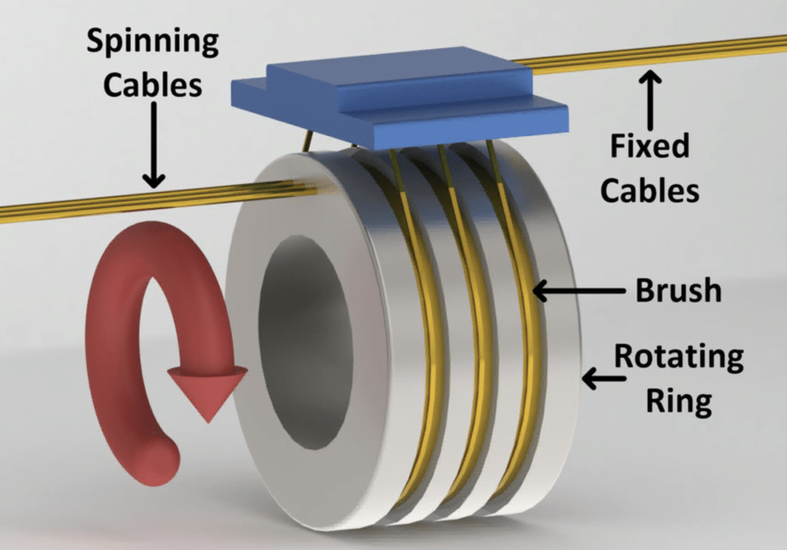
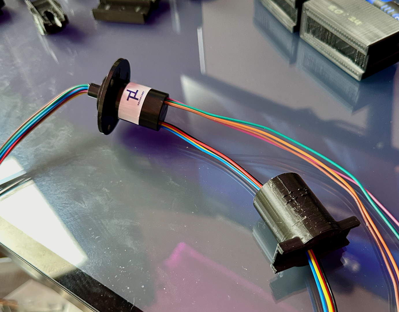
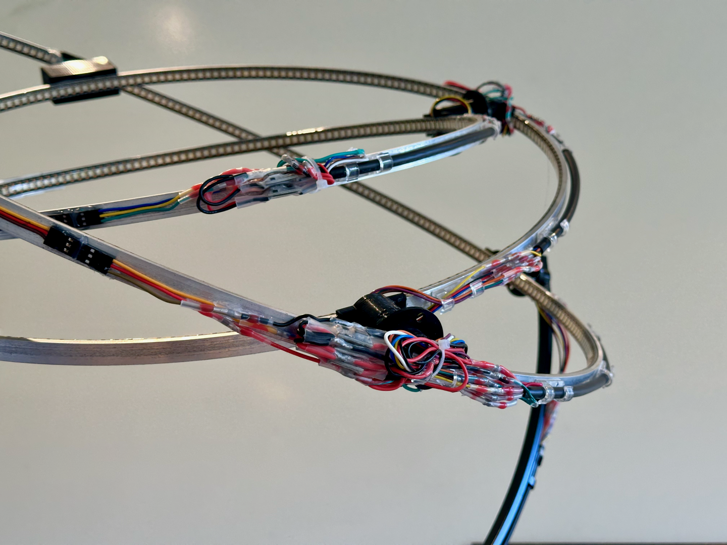
Next, I needed to figure out how get power transmission across a continuously rotating joint. There are a lot of things in everyday life that spin and transmit power but I’d never given a ton of thought to how this might be done before starting this project. This is done using a device called a slip ring, consisting of conductive brushes on the stator that run across a rotating metal rotor, to transmit multiple channels of electrical signals across a rotating joint:
In addition to transmitting signals across rotating joints, each ring would need to spin its immediate internal neighbor using a continuous-rotation servo motor. To decide what servos to buy, I needed to have a rough idea of how powerful they would need to be. I needed to minimize the servo power because the weight of the more powerful, heavier servos would increase the angular momentum of each spinning ring, which in turn makes the servos require greater torque/more power to change the direction of spin. (Additionally, it would result in worse wobbling when the rings are mounted on a pole.)
A quick physics detour: when you have something that is spinning, it has an angular momentum vector \(\vec{L}\) that points normal to its rotation direction. If you want to change the direction this vector points in, it requires a torque of \(\vec{\tau} = d \vec{L} / d t\). (If you’ve ever done the physics demo where you sit on a spinny chair holding a rotating bicycle wheel, you know how this works.) In the case that the angular momentum vector rotates normal to itself uniformly with some precessional angular velocity \(\vec{\Omega}\), then \(\vec{\tau} = \vec{L} \times \vec{\Omega}\). The weight of each ring is about 200g, so if we include the weight of the electronics we would be attaching we can call it 300g, and the middle one is 20 inches in diameter. So if we want the rings to spin at one revolution per second, then \(\vec{L} = I \vec{\omega} = \frac{1}{2}\text{300g} \,(\text{20in})^2 \times 60\text{rpm}\), and if we take this spinning ring and mount it inside another ring spinning at the same velocity, then \(\vec{\tau} = \vec{L} \times \vec{\Omega} = \text{1.53 Nm}\). If we repeat this process again, the calculation gets messier because the moment of inertia \(I\) depends on the angle of the rotating inner ring relative to the outer one, but given that the torques will be orthogonal to each other, \(\tau_0 = \sqrt{2} \tau \approx \text{2 Nm}\) is a good estimate for this. Based on this and some other factors, I ended up choosing to use a trio of MG996R servos, which have metal gears for durability and sufficient torque, but also are relatively lightweight.
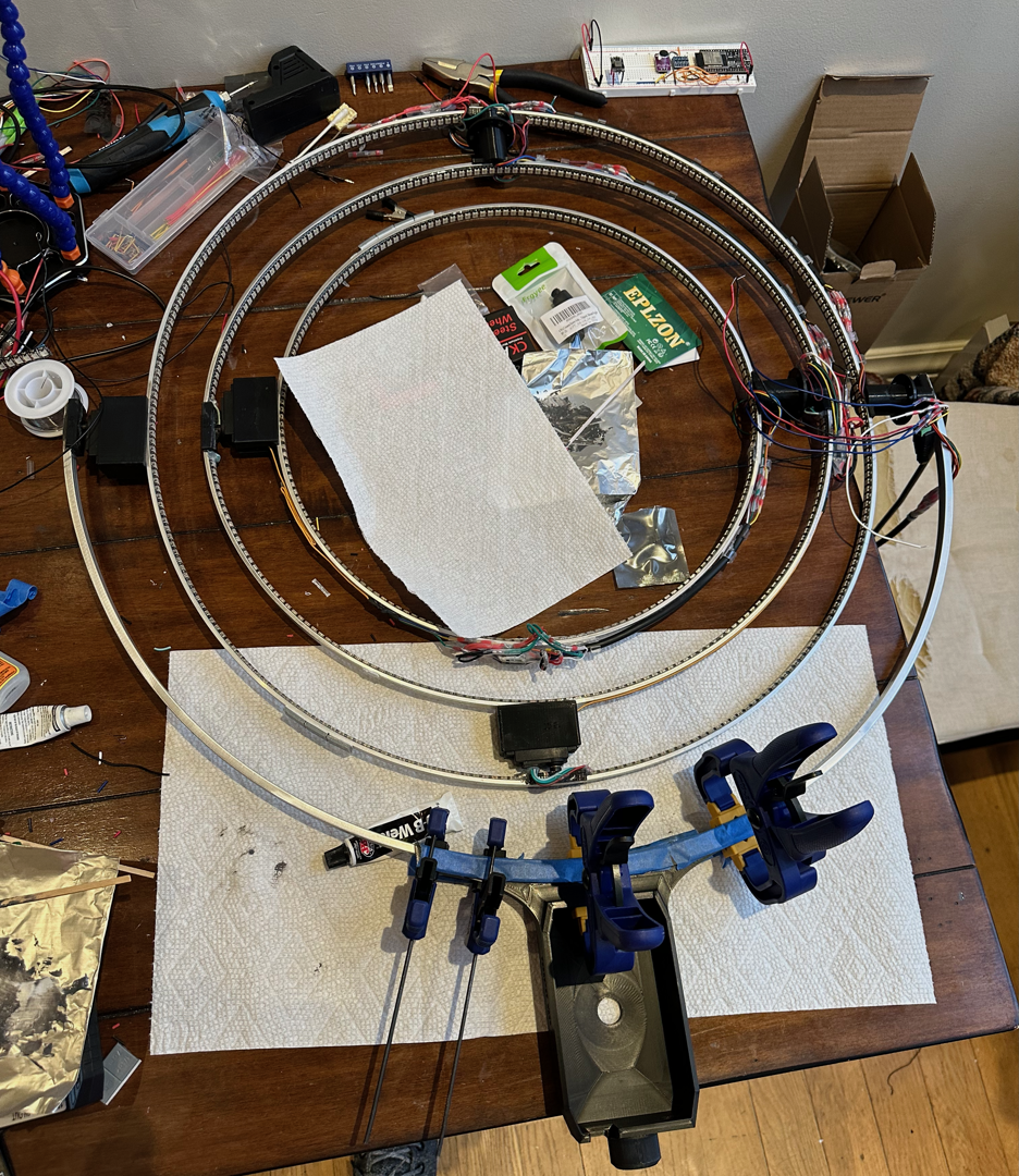
Now I needed to figure out how to couple the rings together. The servo and slip ring ends would need to tightly couple to the rings with a bond that was precise (holding the ring normal to the servo), lightweight, and structurally strong and vibration resistant. I used Fusion to CAD out a design for couplers which I custom-fitted to the servos, slip rings, and radius of curvature of each hoop.
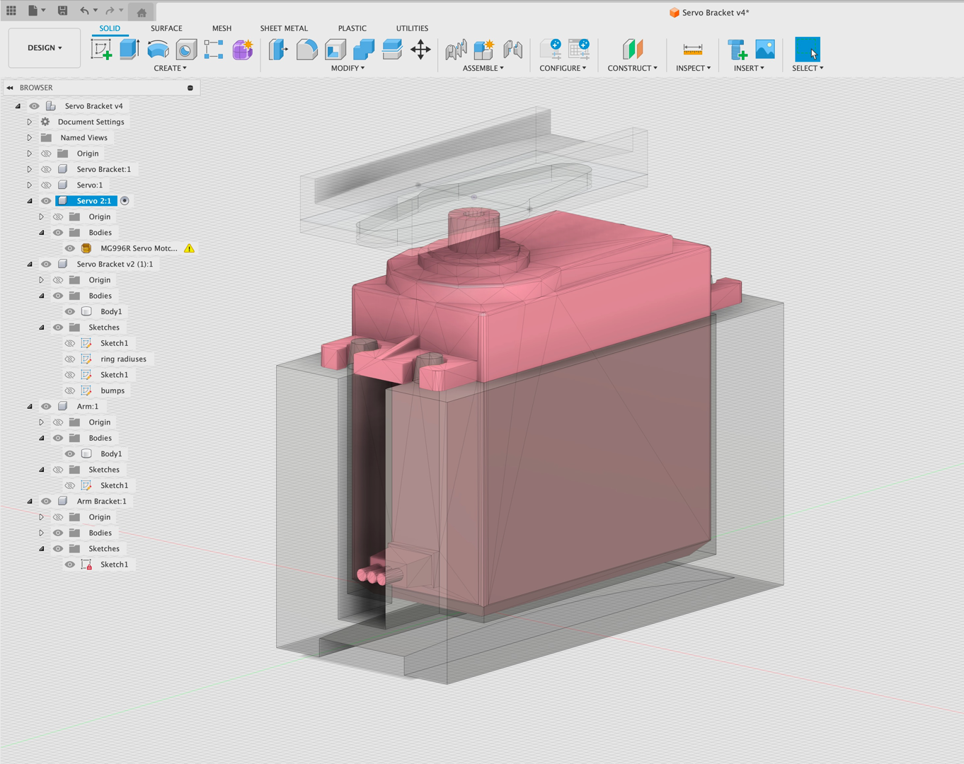
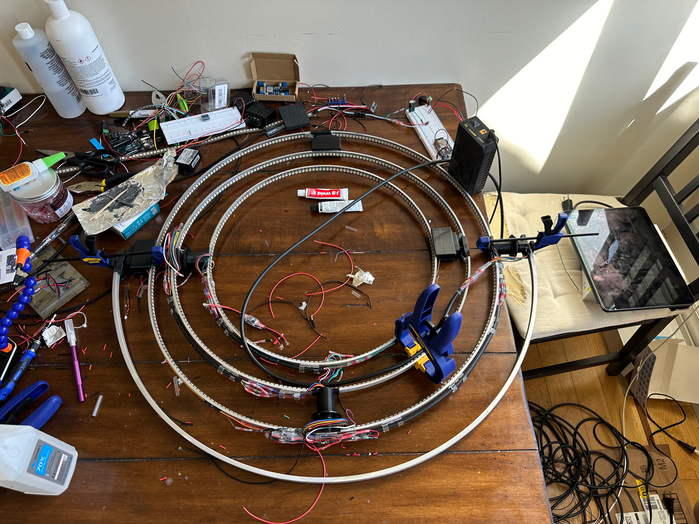
I 3D printed these couplers in strong, dense plastic, then sanded the aluminum rings and plastic at the contact points and JB-welded them together, keeping them pressed with grips. The completed structural assembly could freely rotate:
Next it was time to add the LEDs! I bought a bunch of SK6812 RGBW strips, which have an additional white channel in addition to the normal red, green, and blue channels. I figured since this totem was going to be sound-reactive, it would be nice to have an additional channel to play with for sound-reactive accent effects, so I could leave RGB underneath for the normal patterns it would display.
I soldered all the strips together (which was arduous at times owing to awkward angles and silicone waterproofing) and passed the data line through each subsequent slip rings. I did some measurements of the currents drawn by the strips when running at full brightness under some color-changing patterns, and found a peak current of around 2.2 amps per strip, meaning the entire totem could draw almost 12 amps. After measuring the resistance of each of the slip rings, I ended up deciding to double the channels allocated for power transmission, and arrived at this layout:

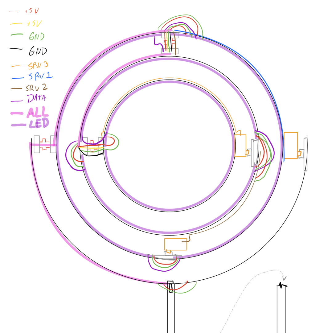
Each ring had about 20-30 joints which needed to be soldered, so I connected most of the wires using heat shrink solder sleeves, which sped up the process considerably.

By this point, I had been working on this project for about a month, and a really exciting moment was when I finally got to turn on the lights and servos!
However, I soon found a problem with my existing setup: I couldn’t drive the lights and servos at maximum power. I had been using the 12V batteries for my burning man bike to power the totem, and I had a large buck converter which stepped the voltage from 12V down to 5V just before injecting it into the outermost ring. However, at 5V, the inherent \(\sim0.5\Omega\) resistance of the slip rings was causing too large of a voltage drop across the rotating joint, so the innermost rings were turning off entirely, unless I severely limited the LED brightness and servo speed. To fix this, I changed the design to running the power lines at 12V, and installed a bunch of tiny buck converters which locally step down the voltage at each ring.
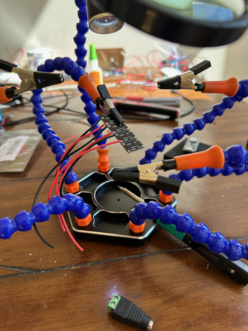
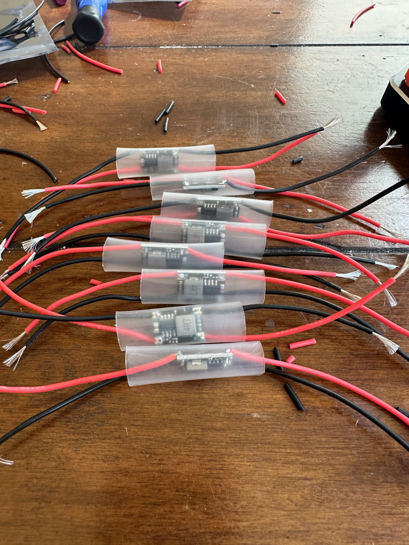
The final electrical design for the totem ended up looking like this:

Now I needed to mount the totem on something! I wasn’t really keen on the idea of having to hold this thing up the entire time I was at EDC, so I ended up buying a reversible tripod which had legs that could fold up to turn the totem a staff configuration. This way I could easily carry it through a crowd, and I can deploy it when I’m not moving and get tired of holding it.
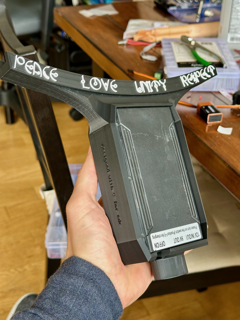
To mount the rotating apparatus, I bought a double-thickness version of the largest ring on the totem at this point and sawed it in half, bending the ring outward slightly so the radius of curvature was 4 inches larger. I designed an integrated mount which would couple the stationary ring to a battery compartment with a metal 1/4”-thread adapter at the base. This way the pole could be removed for added portability when I want to pack this thing in a box to put it in the RV.
I 3D printed the mount/battery holder in the same plastic I used for the servo/slip ring couplers, with some white plastic for accents:
The battery fit in the case perfectly! I bonded the stationary ring to the mount using some trusty JB-weld and finally got to see this thing upright!
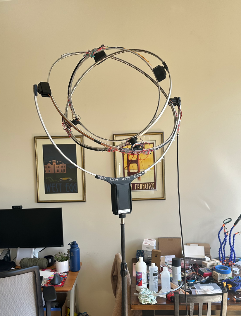
I liked the visual contrast between the silver metal and black plastic on the spinning rings, but since the outer half-ring was stationary and had no lights, I decided the it would look better if it were painted matte black to match the rest of the stand, so I prepped the entire assembly for painting:
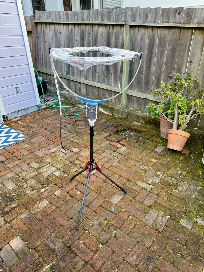
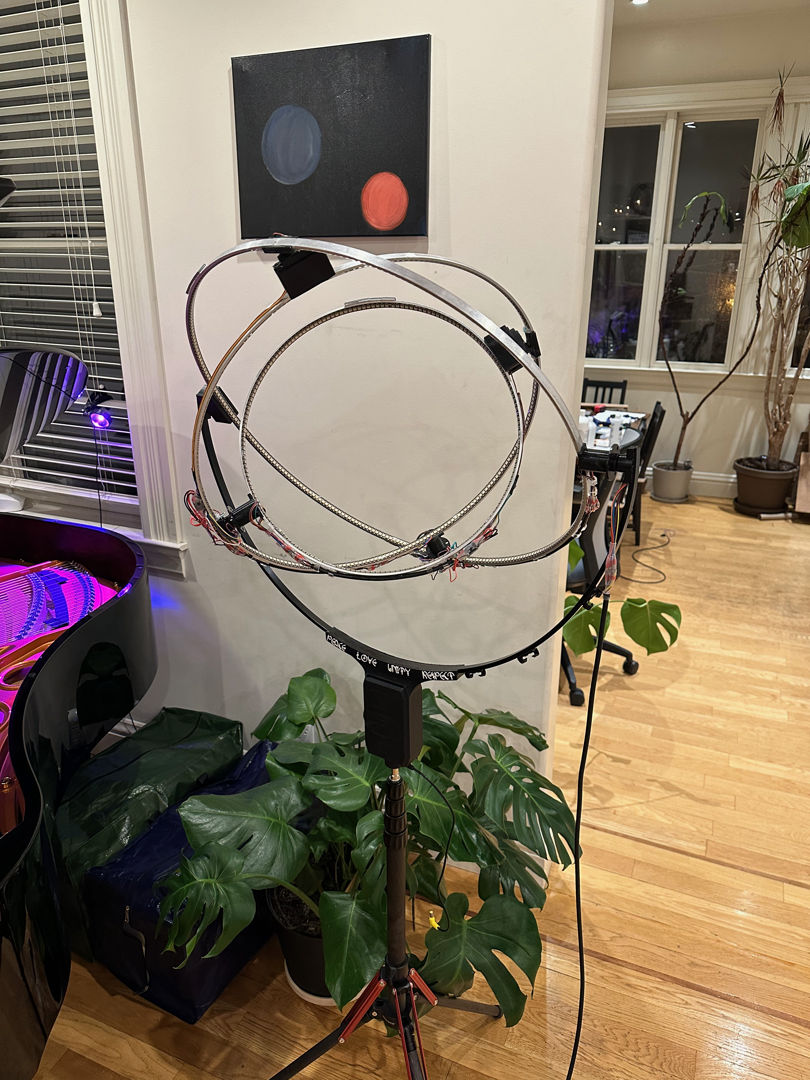
Finally I added a couple of 3-gram counterweights to balance each ring, as counterweight for the asymmetrically distributed electronics. This helped make the totem shake less while the rings were spinning. (The time-varying torque associated with the changing angular momentum of the rings is unavoidable, but this eliminated any additional wobbling due to the balance of the rings.)
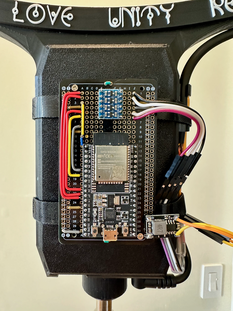
Now it was time to program this bad boy! (You can find all of my code for this project at github.com/bencbartlett/gyroled.) The totem is controlled by an ESP32 (basically an Arduino for grown-ups), which drives the lights and servos, handles bluetooth communications to a custom iOS app I wrote, and performs sound analysis and beat detection to make the light shows music-reactive.
Since the noise level at EDC can vary a lot (how close you are to speakers, what set is playing, whether the crowd is ooh-ooh’ing in the background, etc), the music reactivity needs to be invariant to the ambient volume and filter out things that don’t make you want to dance. The music reactivity algorithm goes something like this: one core of the controller continuously samples from the microphone and writes the outputs to a cyclically rotating buffer. The other core runs the main logic of the controller. At each frame, an FFT is performed on the latest 512 samples, the result is EMA’d with the previous frame’s results (which helps smooth out signal noise), and the frequency bin results are multiplied by a filter which peaks at the 60-100Hz frequencies that most kick drums resonate at. Then, an entropy difference per frame is calculated (sum of squares of differences of each frequency bin), which produces a heuristic that empirically is pretty good at telling you whether there’s a musical event or beat happening on that frame. This heuristic is multiplied by a value that quickly increases from 0.0 immediately after the beat to 1.0 a fraction of a second later, which helps prevent double-counting beats. The beat heuristics per frame are stored in a cyclic buffer, and if the intensity is above some threshold then the device counts it as a beat, updating the value of the last beat and the beat recency filter.
Another feature I am hoping to complete on the RV ride down to Nevada is automatic beat drop detection! The beat heuristics are written to a cyclic buffer which stores about 60 seconds of context. If the totem detects that there hasn’t been beats for a few bars, it assumes that the song has entered a bridge and that a big drop will follow the end of the bridge. So the next beat it detects will cause the totem to freak out, setting motors to max speeds, strobing lights, etc.
After I was happy with the hardware of the controller and tested it to see that it could produce a convincing music-reactive response, I finalized the design of the controller and integrated it onto a solder board (which is like a breadboard but permanent since components are soldered to the board).
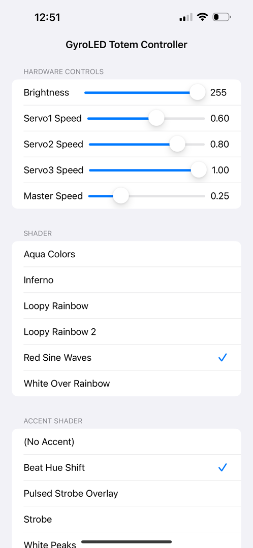
Since the controller would be on a pole high in the air, I didn’t have a physical way to interact with it, so I also wrote a small iOS app to communicate with the controller via Bluetooth to be able to change the shader/servo speeds/brightness/etc. I spent a day developing this and was so excited to turn it on that when I put the headless controller back on the totem and plugged it in to the battery, I accidentally plugged ground into 12V input and 12V into ground and fried the entire controller. (A few hours of soldering another controller later, I carefully plugged it in and was very excited to see that is basically worked out of the box!)
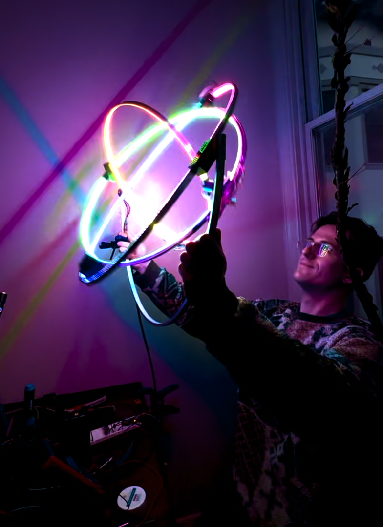
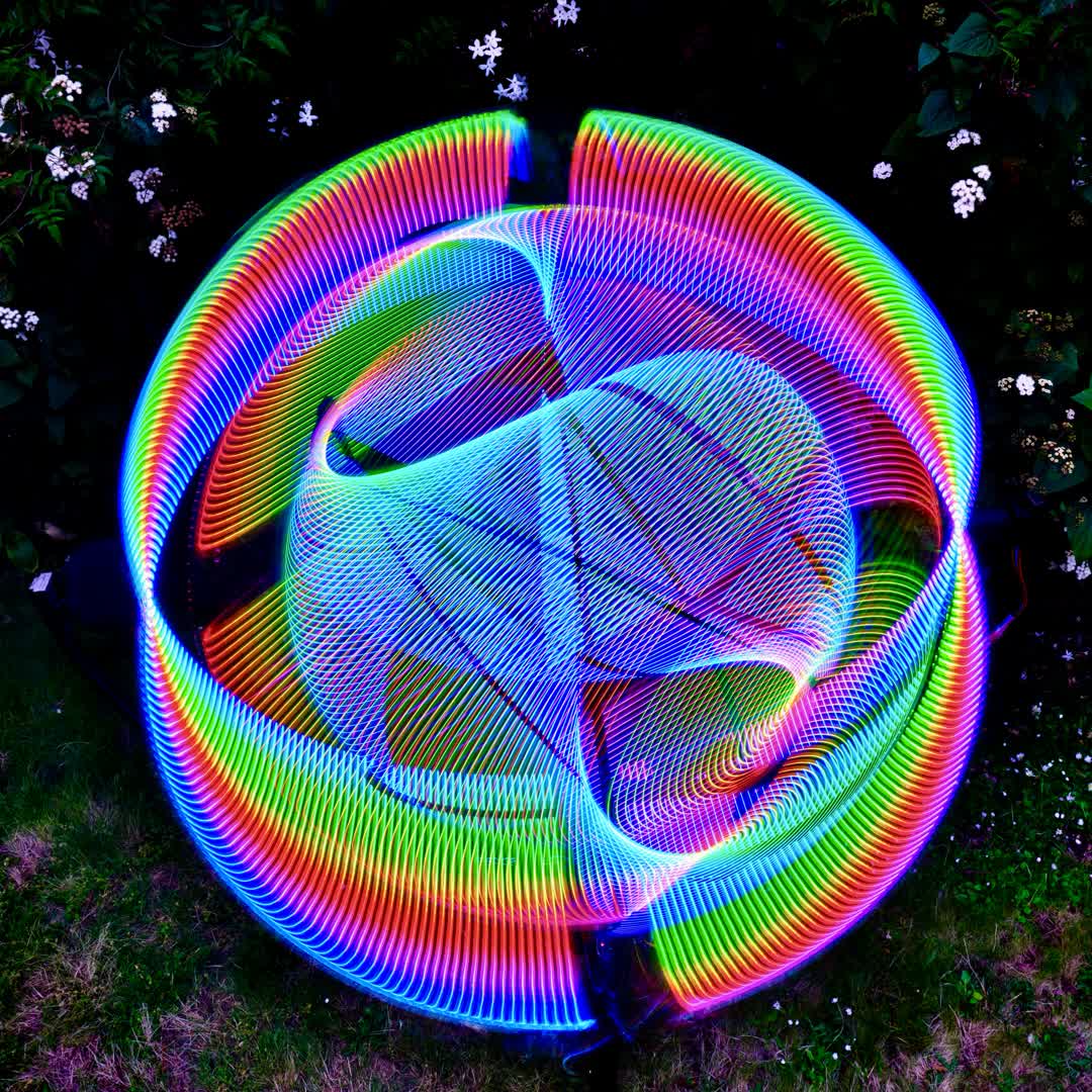
If you’ve made it to this point in this blog post, I hope you’re still interested, so here’s a collection of action shots:
I had a ton of fun building this project and I’m so excited to get to test it out under the electric sky!
Updates: some post-EDC action shots!
